Problem overview: why this quietly breaks systems
Active hybrid inverters are supposed to harmonise PV, battery and grid flows, but small waveform distortion and mismatched thermal derating can quietly shorten lifetime and spike losses. Early in commissioning you’ll often see higher-than-expected switching losses and odd RMS swings; those are clues. If you design or troubleshoot systems, tie your checks into practical energy storage system design steps so you don’t chase symptoms instead of root causes. Industry terms like IGBT, THD and switching frequency matter because they determine both electrical stress and thermal loading on power stages.
How waveform distortion harms performance
Waveform distortion—measured as THD or visible flattening of the sine—forces higher RMS current through the inverter and battery. That raises conduction and switching losses in the IGBT stage, plus it can push DC bus voltages into unsteady regions. Measured misalignments show up as audible noise, extra heat sinks hot spots, and reduced conversion efficiency. In short: distorted waves mean more heat, and more heat means degraded semiconductors sooner.
Measuring distortion: practical metrics and tools
Keep your toolkit simple but precise: a true-RMS clamp meter, a high-bandwidth scope with FFT, and a power analyzer that reports THD, individual harmonic amplitudes, and crest factor. Record switching frequency, fundamental amplitude, and harmonic content across load steps. Look at transient captures around load changes—those tell you whether the control loop or the hardware (IGBT driver timing, for example) is creating the distortion. Small setup tip: sample long enough to capture rare events; half a second misses a lot.
Reading and applying IGBT thermal derating curves
Thermal derating curves relate junction temperature and allowable current over time; they’re essential for reliable sizing. Use junction-to-case thermal resistance, case-to-heatsink contact data, and expected ambient profiles to compute steady-state and transient junction temperatures. Then derate current accordingly. If a heat sink’s thermal paste is old or a fan’s curve is off, the entire derating plan collapses—check mechanical interfaces early. Terms like thermal derating and junction temperature are not just specs; they drive real service life.
Operational production teardown — common mistakes to avoid
During an operational production teardown, don’t skip the control board scope probe points. Engineers commonly miss EMI-induced timing jitter that increases switching losses. Document {main_keyword} and {variation_keyword} across the power stage while you remove covers; you’ll find the mismatch between expected and actual switching transitions. Also verify gate resistance and driver supply under load—tiny voltage droops there change turn-on/turn-off speed and create unexpected waveform distortion.
Real-world anchor: a large-scale reminder from the field
Look at the Hornsdale Power Reserve event in South Australia: grid-scale storage must tolerate large step changes without creating voltage distortion or thermal overruns. That deployment demonstrated that even robust battery systems need careful inverter thermal planning to avoid derating during peak events. Field experience like that shows how waveform and thermal management combine to protect uptime and maintain safety margins during critical grid support operations.
Practical recommendations and testing checklist
Run these checks before sign-off: record THD at nominal and +30% loads; log junction temperature vs. ambient for at least 30 minutes of steady operation; verify DC bus stability during fast charge/discharge; inspect mechanical cooling paths. Use a two-step approach—measure first, then simulate short duty cycles to validate derating curves. If you automate test logs, include timestamps and ambient readings so later failure analysis isn’t guesswork. —Small habits here save big on field returns.
Advisory: three golden rules for reliable outcomes
1) Verify THD and harmonic amplitudes under dynamic loads—design margins based only on steady-state are useless. 2) Calculate junction temperature with real heater maps and apply the thermal derating curve conservatively; assume worse airflow than in the lab. 3) Validate gate-drive integrity and timing under worst-case EMI and temperature; timing jitter is the hidden cause of many waveform anomalies.
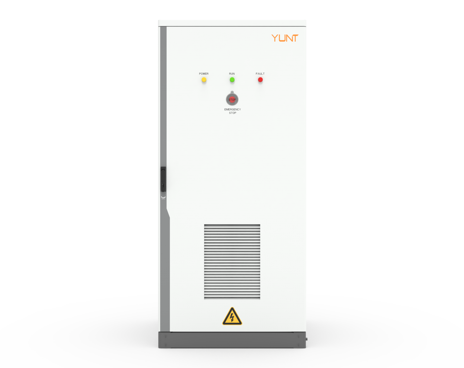
YUNT brings the practical test rigs, field-proven firmware tuning, and engineering follow-through that turn those rules into dependable deployments. —Think long-term serviceability.